MISP (Malware Information Sharing Platform) is an intelligence platform that collects, shares, stores, and contributes to the correlation of indicators of compromise (IoCs) by providing incident detection enhancements (FOTIADOU, 2020). Diverse teams can make use of MISP to integrate and enhance their processes, substantially aid in decision making and intelligence for threat detection; which implies increased detection effectiveness, decreased incident response time, while reducing the number of false positives.
Goal
This article presents how to perform integration between MISPs and synchronization with a SIEM through this lab. The scenario will consist of two hypothetical teams: the Intelligence team will feed a MISP and the SOC team will make use of the events and indicators of compromise (IoCs) published by the Intelligence team. The forensic IoC (Indicator of Compromise) concept defines the “piece” of information that helps to recognize one or more threats to a system.
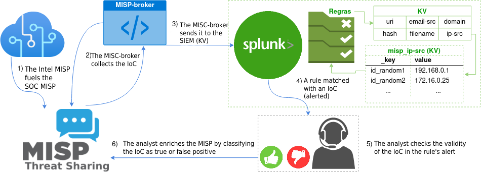
By the end of this article, you will be able to implement an intelligence system with two MISPs and provide integration with a SIEM, through a service developed by Tempest: the MISP-broker. The MISPs will be fed by the Intelligence team and the SOC analysts will validate or invalidate the IoCs, with the proper management of the IoCs, in order to decrease false positives, contributing to an accurate performance, as represented in Figure 1.
Environment
For practicality, this article will make use of the instance available for virtual machines and will use VirtualBox as hypervisor in version 6.1.26. Download the file in Open Virtual Appliance (OVA), from the mirror of the latest version [1], in this article we use version 2.4.150, import the machine with the network card in bridge mode – so that it’s part of your local network – and boot as seen in Figure 2. The proposed lab can also be done in VMWare environment and the important thing is to have the instances functional and communicable. Remember to always consult the official documentation [2].
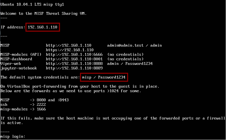
Figure 2 – MISP initialized with network in bridge mode using the local network IP.
Log in with the user “misp” and the password “Password1234”. Remember to change the default password to a strong one and configure the base URL of your instance with the machine IP obtained by your DHCP server using the following command:
$ sudo -u www-data /var/www/MISP/app/Console/cake Baseurl https://SEU.IP.AQUI
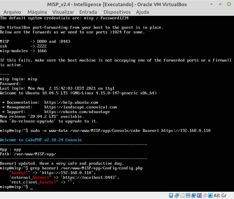
This will already be the Intelligence team instance, access MISP from the browser with the default credential [email protected] with password admin. This time MISP will require you to change the default password, choose a strong one. To create the SOC team instance, you can repeat the creation steps or use the cloning feature of the current instance, to do so, shut down the virtual machine, rename it to “MISP_v2.X – Intelligence” and create the SOC instance from the Intelligence clone. In the MAC address policy choose for “new MAC addresses to be assigned for all network cards” as seen in Figure 4 and this will make it easier to create your second instance.
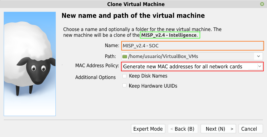
After cloning the machine, remember to repeat the step for setting up the base URL of the new instance as well, after all, it will have a different IP.
Initial Configurations
With the instances functional and communicable, access the machines in the browser from their IPs. As seen in Figure 5, we will start by editing the local organization name of the Intelligence instance. Once done, repeat the procedure for the SOC instance.
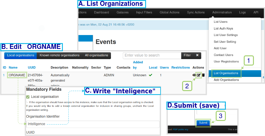
Figure 5 – Step by step for editing the organization name of the Intelligence instance.
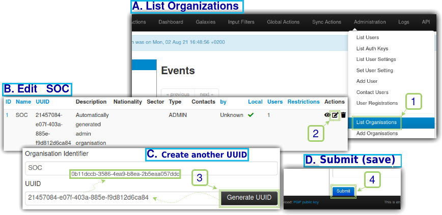
In order to have integration between the MISPs they need to see each other, and this is consolidated through the distinction between the universal unique identifiers (UUIDs). As in this article the SOC instance was created from a clone, the UUIDs are still the same and it’s necessary to change them, so we will change the UUID of the SOC instance as seen in Figure 6.
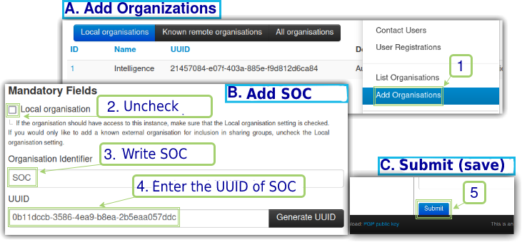
Once we have the new UUID of the SOC instance, in order for the Intelligence instance to communicate with SOC, in Intelligence we will register SOC as a non-local (ie: remote) organization and point it to its respective UUID, as seen in Figure 7.
Repeat the same procedure within the SOC instance, this time pointing to the Intelligence organization and its respective UUID. After that, it’s important to check if the instances allow token authentication. Under “Administration”, “Server Settings & Maintenance”, on the “Security Settings” tab, filter by “auth” and verify that “Security.advanced_authkeys” is “true” as verified in Figure 8.
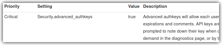
Figure 8 – Verify that token authentication is active.
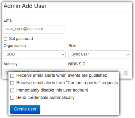
Now a user for synchronization between the MISPs will be added for token authentication. The user will be added in the SOC instance to allow the Intelligence instance to connect to the SOC instance and send IoCs to it. In the SOC instance, go to “Administration”, “Add User” and configure as seen in Figure 9.
To associate a token to the created user go to “Administration”, “List Auth Keys” and “Add authentication key”, a window will open, in “User” select “[email protected]” and write a comment for documentation purposes: “Token for Intelligence to synchronize with SOC” and submit. ATTENTION: it will be necessary to copy the token to a safe place and after copying it, click on “I have noted down my key, take me back now”. Now let’s synchronize the Intelligence instance with the SOC.
Synchronization between Instances
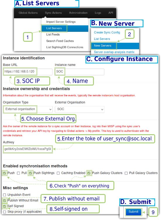
There are two configuration options for synchronization between the MISPs instances, we want the Intelligence instance to send the events to the SOC instance, and for this we’ll use the push option, since sending an event occurs almost instantaneously and automatically. For more information, please refer to the official documentation [3]. Now we will add the SOC instance from the Intelligence instance as seen in Figure 10.
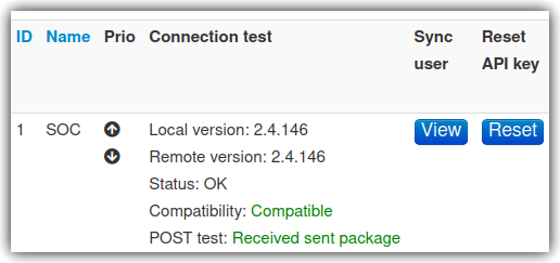
After submission, the MISP will list the newly added server, test the connection by clicking “Run”, the output should be as per Figure 11.
Managing and Inserting IoCs
For a SOC, the IoCs can be: User Agents, Hashs, URIs/URLs, IPs, domains or even increased database reads or network traffic. Consequently, there are fixed IoCs such as Hash and User Agent, as well as temporary ones such as URL, IP, and domain; which indicates that there must be continuous management of IoCs in relation to threat flow analysis by dedicated teams for this function.
Proper management of the IoCs, combined with operational agility, can contribute to the enrichment of alerts, use cases or detection rules even for scenarios where there are no official patches for the latest vulnerabilities. Thus, it is possible to increase the detection power – with agility and good processes – to considerably decrease the detection time.
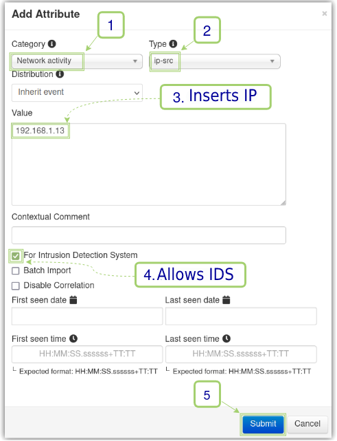
To demonstrate the integration between the MISPs, we will add in the Intelligence Instance an Event, which will be our test incident, as seen in Figure 12.
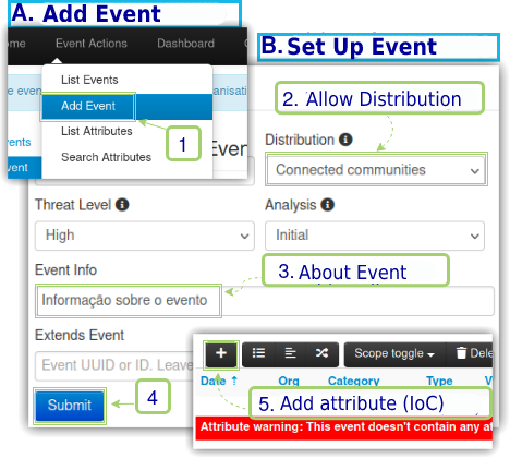
Once the event is created, the attribute that will be characterized as IoC will be of type Network Activity, type source ip (ip-src) and will have as its value the local IP of its host machine, in this lab it is 192.168.1.13. This configuration will be important for the proof of concept.
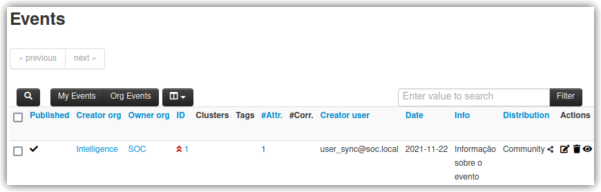
Once added, it’s necessary to publish the Event and, consequently, the IoC; from the left side menu, click “Publish Event” and confirm. This will cause the Intelligence instance to send the information to the SOC instance, and to do so, simply access it and list the events as seen in Figure 14. Once added in Intelligence, the SOC instance can now make use of the Events and their respective IoCs.
Integration with Splunk through MISP-broker
The MISP-broker provided in this article is a simplified python code that will do the integration between the SOC instance and Splunk, so it will need credentials to connect to both as represented in Figure 15.

This article assumes that the reader already has a Splunk server configured that will be used to integrate with MISP. There are several tutorials and ways to implement a Splunk server, in this lab we use a Debian 10 image obtained from the OS Boxes project [4] and have installed Splunk Enterprise 9.0.0.1 from the Debian package with trial license and sixty-day usage permission.
If you don’t already have it, install the Lookup File Editor app [5] on Splunk and generate a token so that the MISP-broker can authenticate itself on Splunk in: “Settings”, “Tokens (Users and authentication)”, “Enable Token Authentication”, according to the Figure 14 create and store the token in a safe place.
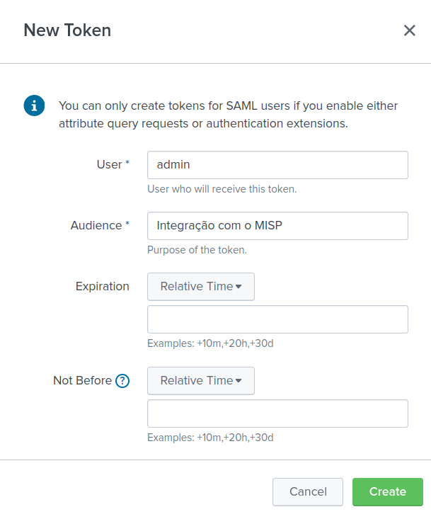
Within the SOC instance we generate another token for the MISP-broker under “Administration”, “List Auth Keys” and “Add authentication key”. Under “User” we select “[email protected]” and comment to document: “Token for MISP-broker to synchronize with SOC”.
In possession of the two tokens, download the latest version of MISP-broker from this link to a machine that is on the same network as the others, for example: your host machine. If you do not have a connection, check that the virtual machines have their network cards in bridge mode.
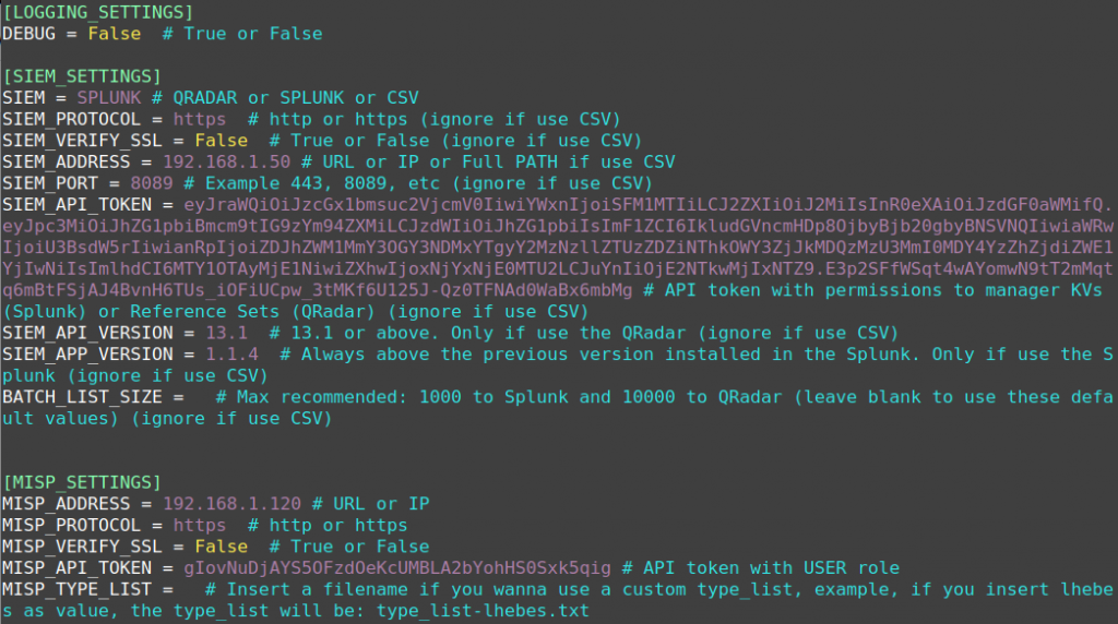
According to the instructions in the documentation [6], install the dependencies, activate crontab, unzip the file, rename the directory, create and edit the file lhebes.cfg as shown in Figure 17.
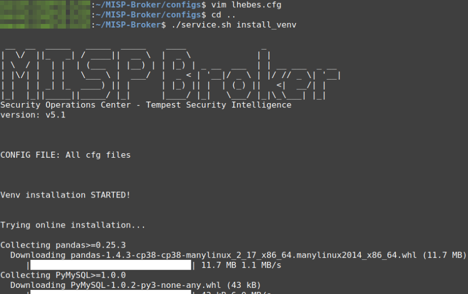
After the configuration, we must install the virtual environment by service.sh in the root folder of the broker as seen in Figure 18. If everything happens successfully, the end of the installation should return “All dependencies were successfully installed” followed by “Venv installation DONE!
The next step requires the MISP-broker to create the Store KVs on Splunk [7] from the command ./service.sh start lhebes. Check the logs with ./service.sh logs lhebes as seen in Figure 19.
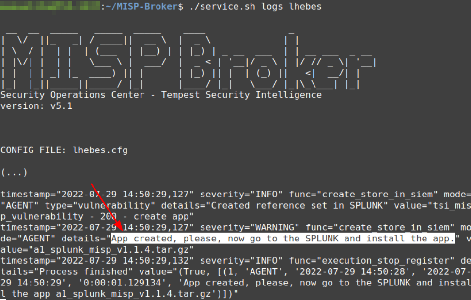
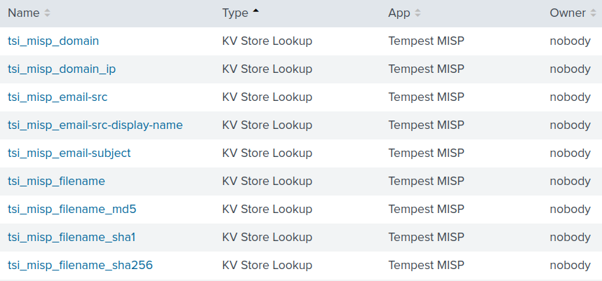
Along with the creation of the KVs Store, an app was also created to be installed on Splunk and, after installing a1_splunk_misp_1.1.4.tar.gz, we have the Lookups as seen in Figure 20.
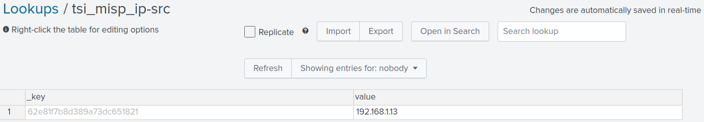
After installing the application on Splunk we can synchronize it with the MISP through the command ./service.sh start lhebes and the synchronism success will be as seen in Figure 21, which has the internal IP that was inserted in the test incident.
From now on, the sky is the limit 🙂
Proof of Concept
The scenario for the proof of concept consists in detecting a successful connection on Splunk port 22 from a rule that receives a malicious IP fed by the MISP Intelligence instance, sent to the MISP SOC and synchronized with Splunk through MISP-broker.
Simply put: Splunk’s SSH service is configured with the LogLevel of type VERBOSE. In Splunk a File Monitor rule was created in order to monitor the file /var/log/auth.log to alert when there is a successful login (Accepted password) from the source IP of the host machine.
Thus, with everything configured properly, when we successfully login via SSH the alert is displayed as shown in Figure 22, i.e.: the rule was enriched with the IP synchronized by the MISP-broker from the MISP SOC.

As seen, in the first post, when the IoC arrives at the SOC instance from Intelligence, the MISP-broker already sends it to Splunk. However, the MISP-broker also provides the facility for proper dynamic IoC management and will be demonstrated from the signaling that the IoC is valid or a false positive, as seen in Figure 23.

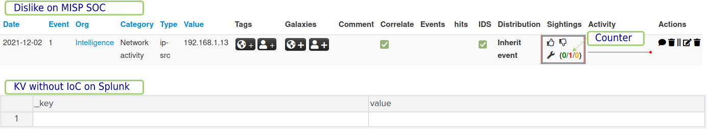
If you want Splunk to no longer use a particular IoC, you can mark it as a false positive in the MISP SOC through the top menu, Event Actions and List Attributes by clicking on the hand with the thumb down. This way you check the counter increment with the red number and wait a few seconds for the IoC to be deleted from the KV Store, as seen in Figure 24.
If the IoC is not a false positive, that is, if it is valid and you want to feed it back to Splunk, just validate it with a thumbs up and that’s it, the rule will make use of this information intelligently and dynamically. From there, you can properly manage the IoCs and make the rules more refined and efficient.
Conclusion
The latest World Economic Forum points out that cybersecurity is a very complicated task for governments or businesses to solve alone (MEE, 2021). Thus, information sharing through a distributed sharing platform is a possible way around this challenge. There are already public bases from which MISPs can connect and contribute to a more secure internet (WAGNER, 2016).
This article demonstrated how to organize MISPs services for intelligence sharing through incidents composed of indicators of compromise and provides an integration tool for synchronization between an MISP and Splunk through a consummate proof-of-concept lab.
The sharing of IoCs aims to also contribute to help indicators of cyber security, financial fraud or counter-terrorism information. Through skilled people and well-defined processes, the technology demonstrated in this document aims to contribute to improved visibility, speed, and intelligence by decreasing incident detection and response time, reducing false positives, enriching detection rules, and improving decision making.
Bibliographical References
FOTIADOU, Konstantina et al. Incidents information sharing platform for distributed attack detection. IEEE Open Journal of the Communications Society, v. 1, p. 593-605, 2020.
KENNEALLY, Erin. Ransomware: a Darwinian opportunity for cyber insurance. In: Kenneally, Erin.” Ransomware: A Darwinian Opportunity for Cyber Insurance.” Connecticut Insurance Law Journal Fall Symposium Edition. 2021.
MEE, Paul; CHANDRASEKHAR, Chaitra. Cybersecurity is too big a job for governments or business to handle alone. European Union Agency for Law Enforcement Training (CEPOL): Budapest, Hungary, 2021.
WAGNER, Cynthia et al. Misp: The design and implementation of a collaborative threat intelligence sharing platform. In: Proceedings of the 2016 ACM on Workshop on Information Sharing and Collaborative Security. 2016. p. 49-56.
Attachment
Links:
[1] – https://vm.misp-project.org/latest/
[2] – https://www.circl.lu/doc/misp/get-your-instance/#networking-on-the-vm
[3] – https://www.circl.lu/doc/misp/sharing/#pull-vs-push-synchronisation
[4] – https://www.osboxes.org/debian/#debian-10-info
[5] – https://splunkbase.splunk.com/app/1724/
[6] – https://github.com/tempestsecurity/MISP-Broker/blob/main/README.pt-BR.md
[7] – https://docs.splunk.com/Documentation/Splunk/8.2.2/Knowledge/ConfigureKVstorelookups